Support our educational content for free when you purchase through links on our site. Learn more
🔧 Why Functional 3D-Printed Prototypes Are So Popular

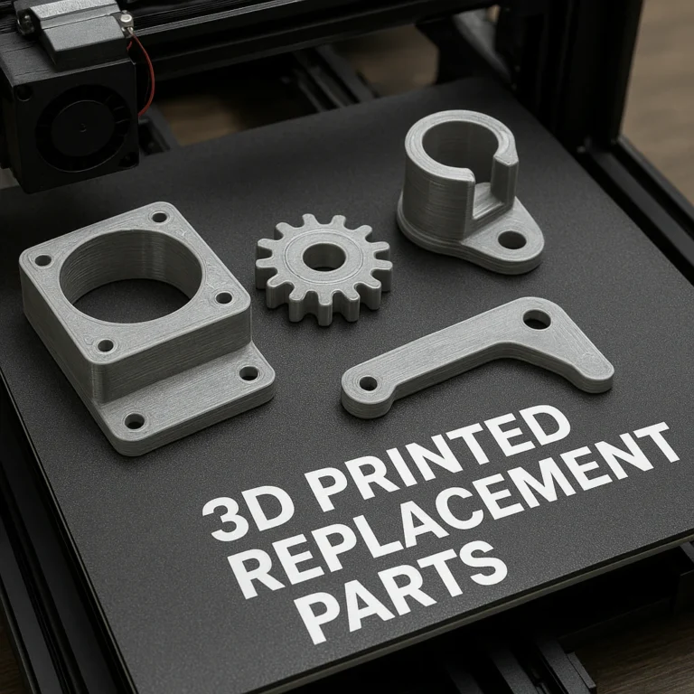
The popularity of 3D-printed functional prototypes comes from a simple advantage: teams can make, test, and revise real parts faster than waiting for production tooling. For fit checks, moving assemblies, enclosures, and fixtures, 3D printing turns a CAD change into something you can hold and evaluate.
We’ve watched a tiny printed bracket save a much larger redesign: it exposed a blocked screw hole before the surrounding assembly was finalized. That’s the appeal—not just making a model quickly, but catching the inconvenient little problems while they’re still easy to fix.
The right process depends on the test. FDM/FFF is a practical starting point for many fit checks, SLA/MSLA offers fine detail and smooth surfaces, and SLS is well suited to complex nylon parts; none makes every prototype production-ready by default.
Key Takeaways
- Rapid iteration drives popularity: Print a part, test it, revise the CAD, and try again without committing to dedicated tooling.
- Choose the process for the test: FDM/FFF suits many basic fit checks; SLA/MSLA excels at detail; SLS is useful for intricate, durable nylon prototypes.
- Material and print orientation matter: Strength, flexibility, heat resistance, and layer direction can change how a prototype performs.
- A prototype answers a specific question: Define what you need to test—fit, load, movement, sealing, or ergonomics—before choosing a printer and material.
- A successful print is not automatically a qualified product: Validate safety, durability, and production requirements separately.
Table of Contents
- ⚡️ Quick Tips and Facts: 3D-Printed Functional Prototypes
- 📈 Why Functional 3D-Printed Prototypes Are So Popular
- From One-Off Models to Real-World Testing
- How 3D Printing Changed Rapid Prototyping
- 🧩 What Counts as a Functional Prototype?
- Functional Prototypes vs. Visual Models and Production Parts
- Prototype Fidelity: Form, Fit, and Function
- 🚀 Why Engineers Choose 3D Printing for Functional Prototyping
- Faster Design Iterations and Shorter Development Cycles
- Complex Geometry, Customization, and Part Consolidation
- On-Demand Production and Supply-Chain Flexibility
- 🖨️ 3D Printing Technologies for Functional Prototypes
- FDM and FF: Affordable Thermoplastic Prototypes
- SLA and MSLA: Fine Detail and Smooth Surface Finish
- SLS: Durable, Complex Nylon Parts Without Supports
- Other Options: MJF, PolyJet, and Metal 3D Printing
- FDM vs. SLA vs. SLS: Comparing Filament, Resin, and Powder
- Using FDM, SLA, and SLS Together in a Prototype Workflow
- Learn More About SLA and SLS Prototyping
- 🧪 Choosing Materials for Functional 3D-Printed Prototypes
- PLA, PETG, ABS, and ASA for Practical Testing
- Nylon, TPU, Polycarbonate, and Engineering Filaments
- Resins and Powder-Based Materials: Strengths and Limitations
- Material Properties: Strength, Heat, Chemicals, and Flexibility
- Matching Prototype Material to the Intended Use
- 📐 Measuring Prototype Quality: Resolution, Accuracy, and Strength
- Resolution and Feature Detail
- Dimensional Accuracy, Precision, and Tolerances
- Anisotropy, Layer Adhesion, and Watertightness
- Surface Finish, Fit, and Functional Interfaces
- 🛠️ Design for Additive Manufacturing
- Wall Thickness, Clearances, Threads, and Snap Fits
- Supports, Overhangs, Orientation, and Part Splitting
- Designing for Load, Fatigue, Heat, and Impact
- CAD and Slicing Software for Prototype Design
- 🔄 The Functional Prototyping Workflow
- Define Requirements and Choose a Test Plan
- Prepare CAD Files and Select Print Settings
- Print, Post-Process, Assemble, and Test
- Document Results and Iterate the Design
- ⚙️ Printer Performance: Build Volume, Speed, and Ease of Use
- Build Volume and Part Size
- Print Speed, Throughput, and Batch Production
- Reliability, Calibration, and Workflow Considerations
- 🧽 Post-Processing Functional Prototypes
- Support Removal, Sanding, and Surface Finishing
- Resin Washing and Curing
- Dyeing, Sealing, Inserts, and Assembly
- 💰 Costs, Business Value, and Return on Investment
- In-House Printing vs. Outsourced Prototyping
- Total Cost: Materials, Labor, Equipment, and Reprints
- How Rapid Prototyping Reduces Development Risk
- 🏭 Industries Using 3D-Printed Functional Prototypes
- Product Design, Consumer Electronics, and Appliances
- Automotive, Aerospace, and Transportation
- Medical Devices, Dental, and Healthcare
- Robotics, Manufacturing, and Industrial Equipment
- ⚠️ Limitations, Risks, and Common Prototyping Mistakes
- When 3D Printing Is Not the Right Prototyping Method
- Avoiding Weak Prints, Poor Fits, and Misleading Test Results
- Safety, Material Handling, and Ventilation
- 🔮 The Future of Functional 3D-Printed Prototyping
- Advanced Materials and Multi-Material Printing
- Automation, AI, and Digital Manufacturing
- ✅ Conclusion
- 🔗 Recommended Links
- ❓ FAQ
- Why are 3D-printed functional prototypes so popular?
- Which 3D printing technology is best for functional prototypes?
- What is the strongest material for a 3D-printed prototype?
- Can a 3D-printed prototype be used as a final product?
- How accurate are functional 3D-printed prototypes?
- How do you reduce the cost of rapid protyping?
- 📚 Reference Links
Table of Contents
- ⚡️ Quick Tips and Facts: 3D-Printed Functional Prototypes
- 📈 Why Functional 3D-Printed Prototypes Are So Popular
- From One-Off Models to Real-World Testing
- How 3D Printing Changed Rapid Prototyping
- 🧩 What Counts as a Functional Prototype?
- Functional Prototypes vs. Visual Models and Production Parts
- Prototype Fidelity: Form, Fit, and Function
- 🚀 Why Engineers Choose 3D Printing for Functional Prototyping
- Faster Design Iterations and Shorter Development Cycles
- Complex Geometry, Customization, and Part Consolidation
- On-Demand Production and Supply-Chain Flexibility
- 🖨️ 3D Printing Technologies for Functional Prototypes
- FDM and FF: Affordable Thermoplastic Prototypes
- SLA and MSLA: Fine Detail and Smooth Surface Finish
- SLS: Durable, Complex Nylon Parts Without Supports
- Other Options: MJF, PolyJet, and Metal 3D Printing
- FDM vs. SLA vs. SLS: Comparing Filament, Resin, and Powder
- Using FDM, SLA, and SLS Together in a Prototype Workflow
- Learn More About SLA and SLS Prototyping
- 🧪 Choosing Materials for Functional 3D-Printed Prototypes
- PLA, PETG, ABS, and ASA for Practical Testing
- Nylon, TPU, Polycarbonate, and Engineering Filaments
- Resins and Powder-Based Materials: Strengths and Limitations
- Material Properties: Strength, Heat, Chemicals, and Flexibility
- Matching Prototype Material to the Intended Use
- 📐 Measuring Prototype Quality: Resolution, Accuracy, and Strength
- Resolution and Feature Detail
- Dimensional Accuracy, Precision, and Tolerances
- Anisotropy, Layer Adhesion, and Watertightness
- Surface Finish, Fit, and Functional Interfaces
- 🛠️ Design for Additive Manufacturing
- Wall Thickness, Clearances, Threads, and Snap Fits
- Supports, Overhangs, Orientation, and Part Splitting
- Designing for Load, Fatigue, Heat, and Impact
- CAD and Slicing Software for Prototype Design
- 🔄 The Functional Prototyping Workflow
- Define Requirements and Choose a Test Plan
- Prepare CAD Files and Select Print Settings
- Print, Post-Process, Assemble, and Test
- Document Results and Iterate the Design
- ⚙️ Printer Performance: Build Volume, Speed, and Ease of Use
- Build Volume and Part Size
- Print Speed, Throughput, and Batch Production
- Reliability, Calibration, and Workflow Considerations
- 🧽 Post-Processing Functional Prototypes
- Support Removal, Sanding, and Surface Finishing
- Resin Washing and Curing
- Dyeing, Sealing, Inserts, and Assembly
- 💰 Costs, Business Value, and Return on Investment
- In-House Printing vs. Outsourced Prototyping
- Total Cost: Materials, Labor, Equipment, and Reprints
- How Rapid Prototyping Reduces Development Risk
- 🏭 Industries Using 3D-Printed Functional Prototypes
- Product Design, Consumer Electronics, and Appliances
- Automotive, Aerospace, and Transportation
- Medical Devices, Dental, and Healthcare
- Robotics, Manufacturing, and Industrial Equipment
- ⚠️ Limitations, Risks, and Common Prototyping Mistakes
- When 3D Printing Is Not the Right Prototyping Method
- Avoiding Weak Prints, Poor Fits, and Misleading Test Results
- Safety, Material Handling, and Ventilation
- 🔮 The Future of Functional 3D-Printed Prototyping
- Advanced Materials and Multi-Material Printing
- Automation, AI, and Digital Manufacturing
- ✅ Conclusion
- 🔗 Recommended Links
- ❓ FAQ
- Why are 3D-printed functional prototypes so popular?
- Which 3D printing technology is best for functional prototypes?
- What is the strongest material for a 3D-printed prototype?
- Can a 3D-printed prototype be used as a final product?
- How accurate are functional 3D-printed prototypes?
- How do you reduce the cost of rapid protyping?
- 📚 Reference Links
Quick Tips and Facts: 3D-Printed Functional Prototypes
A functional prototype is more than a model that looks convincing on a desk. It is a part you can fit, assemble, load, flex, seal, or test in conditions that resemble its intended job. That distinction explains much of the growing interest in 3D-printing statistics and adoption: teams can make a design, test it, adjust the CAD, and print the next revision without waiting for conventional tooling.
| Quick fact | What it means for your prototype |
|---|---|
| “Functional” depends on the test | A snap-fit sample needs suitable flex and fatigue behavior; a bracket needs load-bearing strength; an enclosure may need dimensional accuracy and sealing. |
| FDM/FFF is a practical first pass | Filament printing is often a sensible way to check size, assembly, and basic handling. Layer direction can affect strength. |
| SLA/MSLA prioritizes detail and finish | Resin printing can produce fine features and smooth surfaces, but resin type and post-curing affect mechanical performance. |
| SLS is well suited to complex nylon parts | The surrounding powder supports the geometry during printing, so separate support structures are usually unnecessary. |
| Material choice can matter more than printer resolution | A beautifully detailed prototype made from the wrong material can give you a beautifully detailed wrong answer. |
| Prototype parts are not automatically production-qualified | Validate safety, lifespan, environment, and manufacturing requirements before relying on a printed part. |
Quick recommendations
- ✅ For inexpensive fit checks: Start with PLA or PETG on an FDM/FFF printer.
- ✅ For detailed, smooth parts: Consider SLA/MSLA, then choose a resin based on the actual test—not just its marketing name.
- ✅ For robust, intricate nylon prototypes: Look at SLS or MJF, especially if support cleanup would be awkward.
- ✅ For load tests: Print representative test coupons and parts in the intended orientation. Don’t assume a material datasheet describes every print setting.
- ❌ Don’t use a cosmetic prototype to claim structural performance.
- ❌ Don’t treat “high resolution” as a synonym for “high strength.”
- ❌ Don’t skip assembly trials. A few tenths of a millimeter can be the difference between a satisfying click and a part that needs a hammer—and possibly an apology.
📈 Why Functional 3D-Printed Prototypes Are So Popular
The popularity of functional 3D-printed prototypes comes down to a useful combination: fast design changes, accessible fabrication, and the ability to test real geometry before investing in production tooling. A prototype can reveal a blocked screw hole, awkward grip, weak clip, or badly routed cable while the design is still easy to change.
Formlabs describes 3D printers as having moved “from early adopter novelties to integral parts of design, engineering, and manufacturing workflows in every industry.” That perspective reflects a shift from printing display models to using parts in engineering reviews, fit checks, fixtures, and selected functional tests.
But “popular” does not mean one printer process has won every job. FDM, SLA, SLS, and other additive processes each solve different problems. The winning workflow is often a mix of technologies, not a winner-takes-all contest.
From One-Off Models to Real-World Testing
Early prototypes often answer visual questions: Does this look right? Is the form too bulky? A functional prototype asks harder ones:
- Does the connector fit the mating component?
- Does a hinge survive repeated movement?
- Can the enclosure protect its electronics?
- Does a bracket hold a specified load?
- Can an operator reach the control while wearing gloves?
- Does the part interfere with assembly or maintenance?
A prototype becomes valuable when its test is specific. A print that merely resembles the product may be useful for a design review, but it cannot prove fatigue life, chemical resistance, or long-term safety by appearance alone.
We’ve seen small teams get especially good value from printing practical “boring” parts: drill guides, cable clips, ergonomic grips, alignment jigs, and enclosure revisions. They may never make a dramatic product photo, but they can catch a design problem before that problem gets copied into a batch of expensive parts.
How 3D Printing Changed Rapid Prototyping
Traditional protyping methods remain useful. CNC machining can make accurate parts from engineering materials; casting and injection molding can represent production processes more closely. But additive manufacturing makes it relatively easy to revise a part’s geometry and make another iteration from a digital file.
That makes 3D printing attractive for:
- Early design reviews: Check size, shape, clearances, and assembly.
- Engineering tests: Compare wall thicknesses, clips, ribs, and mounting options.
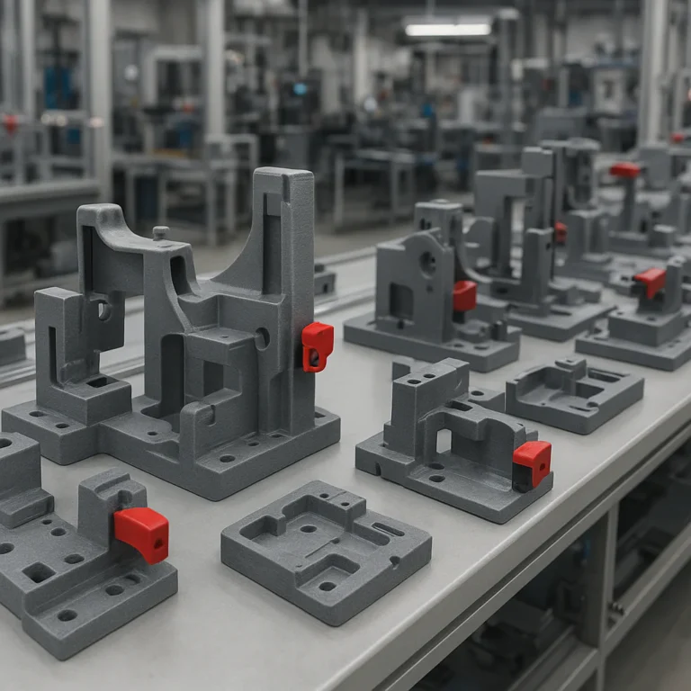
- Manufacturing support: Produce fixtures, guides, covers, and low-volume tools.
- Bridge production: Make limited quantities while a conventional manufacturing process is prepared.
- Customization: Adapt a part to a particular user, device, or installation.
The trade-off is that printed parts carry the characteristics of their process. Layer lines, orientation, resin curing, powder conditions, and post-processing can all affect results. As Formlabs’ process comparison explains, the right choice depends on the part’s requirements, quantity, and manufacturing workflow—not on a single universal ranking.
🧩 What Counts as a Functional Prototype?
A functional prototype is a prototype built to evaluate one or more aspects of how a product works. It might test fit, movement, ergonomics, load, airflow, assembly, sealing, or interaction with other components.
The label is not a guarantee of performance. A printed part can be useful for a functional test without being suitable for sale or permanent service. Think of a prototype as a question made physical: if the test is poorly defined, the answer may be misleading.
Functional Prototypes vs. Visual Models and Production Parts
| Part type | Main purpose | Typical checks | What it does not automatically prove |
|---|---|---|---|
| Visual model | Show appearance, scale, or form | Styling, layout, presentation | Mechanical strength or durability |
| Fit prototype | Check assembly and interfaces | Clearances, screw locations, alignment | Long-term wear or production repeatability |
| Functional prototype | Test specified performance | Load, motion, grip, airflow, sealing | Production compliance or lifespan without validation |
| Production part | Serve in the final product | Reliability, specifications, compliance, repeatability | Nothing beyond the evidence actually tested |
For instance, an FDM enclosure may be excellent for checking whether a circuit board fits. It might still be a poor choice for a leak test if the print has gaps between layers. Likewise, a smooth resin snap-fit could look excellent but fail if the resin is too brittle for repeated deflection.
Prototype Fidelity: Form, Fit, and Function
A useful way to scope a prototype is to decide which kind of fidelity you need:
- Form fidelity: Does the shape, size, and user-facing appearance match the concept?
- Fit fidelity: Do fasteners, inserts, mating parts, and assemblies fit?
- Functional fidelity: Does it behave appropriately under the intended test?
- Material fidelity: Does its material reproduce the relevant production behavior?
- Process fidelity: Does it represent the manufacturing method planned for the final part?
You may not need all five at once. A low-cost FDM print could confirm a hand grip’s size; a more precise SLA or SLS version could follow for assembly or mechanical testing. Define the test first, then decide what fidelity is worth paying for in time and effort.
🚀 Why Engineers Choose 3D Printing for Functional Prototyping
Enginers choose additive manufacturing because it can shorten the distance between “we think this design works” and “we tested the actual geometry.” It also makes it practical to compare multiple revisions rather than arguing over CAD screenshots.
The best case is not always a dramatic breakthrough. Sometimes a quick printed spacer reveals that a sensor is 2 mm too close to a moving arm. That tiny discovery can save a whole afternoon of assembly trouble.
Faster Design Iterations and Shorter Development Cycles
When a prototype is printed in-house ordered from a service, an engineer can often test a revision without making a dedicated mold. That is especially useful early in development, when dimensions and features are still changing.
A disciplined iteration loop looks like this:
- Identify a clear design question.
- Change only the features relevant to that question.
- Print the test part using a documented material and orientation.
- Measure or test it against defined acceptance criteria.
- Record what happened.
- Update the CAD and repeat.
This avoids the classic “we changed six things, and now we don’t know which one fixed it” problem.
Complex Geometry, Customization, and Part Consolidation
Additive processes can make geometries that are inconvenient or costly to produce with conventional methods, such as internal passages, integrated brackets, lattice features, and highly customized shapes. SLS and MJF are particularly useful for complex polymer parts because unfused powder supports the part during printing.
Yet complexity is not automatically an advantage. A thin internal channel that cannot be inspected or cleaned may be worse than a simpler design. Use complex geometry when it improves function, reduces assembly, or enables a test that matters.
For printable accessories and practical fixtures, browse our 3D Printable Objects category. For product design and CAD tools, see 3D Design Software.
On-Demand Production and Supply-Chain Flexibility
A digital file can be revised and printed near the point of need, which can help teams make replacement tools, custom fixtures, and limited quantities without maintaining a large stock of every variant. This is useful when demand is uncertain or the design has not yet settled.
There are limits. On-demand printing still depends on material availability, production capacity, quality control, and the need to verify each part. For a highly regulated or safety-critical use, a digital manufacturing route needs controlled files, traceability, and process validation—not just a printer and a good idea.
🖨️ 3D Printing Technologies for Functional Prototypes
The three familiar polymer processes—FDM/FFF, SLA/MSLA, and SLS—make a useful starting point. They differ in how they build parts, which influences detail, surface finish, strength, materials, and cleanup.
Formlabs’ comparison of FDM, SLA, and SLS notes that businesses commonly use multiple technologies. That matches our practical experience: one printer can handle a quick fit check while a different process makes the final test piece.
FDM and FF: Affordable Thermoplastic Prototypes
FDM (fused deposition modeling), often called FF (fused filament fabrication), melts thermoplastic filament and lays it down in successive paths. It is popular with hobbyists, schools, makerspaces, and businesses because the basic workflow is familiar and material choices are broad.
Strengths
- Accessible workflow for quick design iterations.
- Useful for brackets, housings, jigs, mock-ups, and low-risk fit checks.
- Thermoplastics such as PLA, PETG, ABS, and TPU are widely available.
- Parts can often be modified with common tools and hardware.
Limitations
- Layer lines are visible, and strength can depend heavily on orientation.
- Supports and bridging may complicate overhangs and internal geometry.
- Dimensional consistency depends on printer calibration, material, and settings.
- Some engineering filaments require a suitable hot end, heated chamber, or controlled environment.
FDM is a strong first choice when cost, speed, and convenience matter more than a polished finish or highly predictable mechanical behavior. For a heavily loaded clip or fluid-tight enclosure, test the real print rather than assuming the filament label tells the whole story.
SLA and MSLA: Fine Detail and Smooth Surface Finish
SLA cures liquid photopolymer resin using light. MSLA uses a light source and masking screen to expose a layer. Both can produce detailed parts with smooth surfaces, making them useful for intricate components, fit checks, housings, and models where finish matters.
Formlabs notes that SLA can produce smooth surfaces and tight tolerances and offers resins with different properties. The caveat: “resin” is not one material. Standard, tough, flexible, high-temperature, and engineering resins can behave very differently.
Strengths
- Fine detail and smooth surface appearance.
- Useful for small features and intricate parts.
- Broad specialist resin families for different applications.
- Can provide consistent mechanical behavior when the resin is properly printed and cured.
Limitations
- Parts need washing and post-curing according to the material maker’s instructions.
- Uncured resin requires careful handling and appropriate protective measures.
- Some resins are brittle or sensitive to UV exposure and heat.
- Support marks and orientation can affect surfaces and dimensions.
SLA/MSLA is a compelling option when appearance and detail are important, but the test material must match the intended use. A beautiful standard-resin prototype is not a substitute for a toughened-resin test if the part must flex.
SLS: Durable, Complex Nylon Parts Without Supports
SLS fuses polymer powder—commonly nylon—using a laser. The surrounding unfused powder supports the part during printing, allowing complex geometry without conventional support structures.
Formlabs calls SLS a popular choice for functional prototypes and end-use production, citing the process’s low cost per part, productivity, and established materials in its materials guide. That is a strong case for batch work and intricate designs, though equipment and powder handling make the overall workflow different from a desktop filament printer.
Strengths
- Support-free printing enables complex forms and nested builds.
- Nylon parts can be strong, durable, and useful for functional evaluation.
- Batch production can make good use of the build chamber.
- Surface finish is generally consistent, though not glossy straight from the machine.
Limitations
- Powder handling, depowdering, and finishing add workflow steps.
- Material selection is narrower than in FDM or resin printing.
- Parts may need dyeing, sealing, or surface treatment for a particular use.
- The part’s properties still depend on material, build conditions, and post-processing.
SLS is especially attractive when a part must combine complex geometry with practical mechanical performance. The powder bed is helpful, but it does not make every thin wall or snap-fit automatically successful.
Other Options: MJF, PolyJet, and Metal 3D Printing
| Process | Typical appeal | Useful prototype tasks | Main consideration |
|---|---|---|---|
| MJF | Polymer parts with productive batch workflows | Functional housings, brackets, low-volume parts | Material and surface behavior depend on the specific system |
| PolyJet | Fine detail and multiple material properties | Visual and ergonomic models, multi-material demonstrations | Material behavior may not represent a production polymer |
| Metal powder-bed processes | Metal parts with complex geometry | High-performance components and process evaluation | Requires specialized equipment, safety controls, and post-processing |
| Material extrusion with reinforced filament | Stiff or reinforced parts | Fixtures, tooling, selected load-bearing prototypes | Fiber reinforcement can affect strength by direction and machining |
These processes can be valuable, but they are not required for every prototype. Start with the test requirement and the material properties you need to reproduce.
FDM vs. SLA vs. SLS: Comparing Filament, Resin, and Powder
| Feature | FDM/FFF | SLA/MSLA | SLS |
|---|---|---|---|
| Build material | Thermoplastic filament | Photopolymer resin | Polymer powder |
| Typical draw | Accessible, versatile, practical | Fine detail and smooth surfaces | Complex, durable parts and batches |
| Support strategy | Printed supports for some geometries | Printed supports, usually removed after printing | Surrounding powder supports the part |
| Surface appearance | Visible layer lines | Smooth, detailed surfaces | Powder-textured surface |
| Mechanical behavior | Often direction-dependent | Resin-dependent; can be consistent when processed correctly | Generally useful for functional nylon parts |
| Post-processing | Support removal; sometimes sanding | Washing and post-curing | Depowdering; optional finishing |
| Good starting use | Fit checks and simple prototypes | Small, detailed parts | Complex nylon components and batches |
There is no honest single winner. FDM tends to make sense for simple parts and quick checks; SLA/MSLA excels at detail and finish; SLS is compelling for robust, intricate polymer parts. Use the process that reproduces the characteristics your test actually needs.
Using FDM, SLA, and SLS Together in a Prototype Workflow
A common workflow progresses from quick and simple to representative and demanding:
- FDM first: Check the broad shape, assembly, and ergonomics.
- SLA/MSLA next: Refine detail, surfaces, and tight interfaces.
- SLS when needed: Test complex nylon geometry or parts that see repeated handling and loads.
- Conventional manufacturing for confirmation: Validate production behavior when the final process differs significantly from 3D printing.
Industry examples illustrate this complementary approach. In Formlabs’ case studies, Labconco uses FDM for lower-cost early prototypes and SLA or SLS for later prototypes, tooling, and production aids; Hyphen combines the processes for different component requirements. These are company-reported examples, not universal performance guarantees, but they show why technology choice often changes as a design matures.
Learn More About SLA and SLS Prototyping
The useful question is not “Which process is best?” It is: Which process lets us run the test we need with the least misleading compromise?
🧪 Choosing Materials for Functional 3D-Printed Prototypes
Material selection should follow the prototype’s job. A part that needs to bend, a part that must resist heat, and a part that only checks fit are asking for different properties.
Formlabs puts it plainly: material choice largely determines whether a printed part has the mechanical, functional, and visual properties needed for its application. See its materials guide for a broad overview. We’d add one practical rule: compare the specific grade and print process, not just the polymer family name.
PLA, PETG, ABS, and ASA for Practical Testing
| Material | Useful for | Watch-outs |
|---|---|---|
| PLA | Shape checks, fixtures, simple prototypes, crisp details | Heat and impact limitations vary by formulation; can be less suitable for prolonged mechanical stress |
| PETG | Brackets, covers, moderate-flex parts, practical enclosures | Can string; settings and cooling influence fit and finish |
| ABS | Heat-resistant housings and functional parts when printed well | Warping and fumes require appropriate printer setup and ventilation |
| ASA | Outdoor or UV-exposed prototypes where weather resistance matters | Can warp; enclosure and process control may help |
These are broad tendencies, not promises. Brand formulations vary, and a part printed with poor layer bonding may fail even if the material’s datasheet looks impressive.
For printable components and maker projects, our 3D Printable Objects library is a useful source of inspiration. For functional testing, modify a model only after checking that the geometry and material suit the test.
Nylon, TPU, Polycarbonate, and Engineering Filaments
- Nylon: Often selected for toughness, wear, and functional parts. It can absorb moisture, which affects printing and dimensional behavior.
- TPU: Flexible filament for seals, bumpers, grips, and compliant components. Shore hardness and print settings matter.
- Polycarbonate: Chosen for strength and heat-related properties in suitable systems, but printing can be demanding.
- Fiber-filled filaments: Carbon- or glass-fiber-filled materials can increase stiffness, but may be abrasive and can be brittle in certain directions.
- PEK and PEI-family materials: High-performance thermoplastics for specialized equipment and applications. They require compatible printers and controlled conditions.
Engineering materials are not a shortcut to engineering validation. Always check the manufacturer’s technical data and print recommendations, then test specimens made with your own printer, orientation, and settings.
Resins and Powder-Based Materials: Strengths and Limitations
Resins offer a wide range of properties, from standard detail-focused formulations tough, flexible, or heat-resistant types. Their limitations include handling requirements, post-curing, and possible aging effects. Follow the resin manufacturer’s safety data and processing instructions.
Powder-based nylon is a popular SLS material because it supports a useful balance of strength, flexibility, and durability. Other powders, including flexible TPU and polypropylene, can suit specialized tasks. Powder processes can produce complex parts without conventional supports, but the parts still need depowdering and may require additional finishing.
Material Properties: Strength, Heat, Chemicals, and Flexibility
| Requirement | What to check in the material data | Prototype test to consider |
|---|---|---|
| Strength | Tensile and flexural properties, test method, orientation | Load test using the intended print orientation |
| Impact resistance | Notched impact data or manufacturer guidance | Drop or impact test under controlled conditions |
| Heat resistance | Heat-deflection or service-temperature information | Test at realistic temperatures and duration |
| Flexibility | Elongation, hardness, fatigue guidance | Repeated bend or compression cycle |
| Chemical exposure | Compatibility charts and safety data | Exposure test using the actual chemical |
| Outdoor use | UV and moisture information | Weathering or representative exposure test |
| Sealing | Porosity and process-specific guidance | Pressure or leak test on the finished part |
A material datasheet is a starting point, not a verdict. Different test standards, print settings, and specimen orientations can produce results that are not directly comparable.
Matching Prototype Material to the Intended Use
Use this sequence to avoid choosing material by color or convenience alone:
- Write down the job. What load, movement, heat, moisture, or chemical exposure will the part face?
- Identify the failure mode. Is the concern cracking, creep, wear, poor fit, deformation, or leakage?
- Choose a process that can represent the test. A low-cost shape check may need only FDM; a fine-detail interface may favor SLA/MSLA.
- Read the specific material data. Check how properties were measured and whether they apply to your print direction.
- Print a test sample. Use the same settings and post-processing planned for the prototype.
- Run the test and record the result. A failed sample is useful evidence if you learn why it failed.
📐 Measuring Prototype Quality: Resolution, Accuracy, and Strength
A prototype is useful only if you can trust what it tells you. That requires separating concepts that are often bundled together: resolution, accuracy, precision, strength, and surface finish.
A printer’s advertised pixel size or layer height does not tell you how accurately every feature will print. Material behavior, calibration, orientation, supports, shrinkage, and post-processing also matter.
Resolution and Feature Detail
Resolution describes the smallest changes a system can represent or produce. In a 3D printer, layer height and in-plane detail are part of the picture, but they are not the whole picture.
A printer may have a small nominal layer height and still struggle with:
- Tiny holes that print undersized.
- Thin walls that break during support removal.
- Fine details lost to resin exposure or nozzle width.
- Sharp corners softened by material flow or post-processing.
Check the manufacturer’s design guidelines and validate critical features with a small test coupon before printing the full assembly.
Dimensional Accuracy, Precision, and Tolerances
- Accuracy: How close a measurement is to the target.
- Precision: How consistently repeated prints match one another.
- Tolerance: The permitted variation for a feature or assembly.
For a moving fit, a clearance that works in one process may not work in another. Build a simple clearance ladder—several versions with gradually changing gaps—and test it with the actual material and printer. This is often more reliable than copying a generic internet tolerance.
A caliper is useful for basic checks; a coordinate-measuring machine or optical system may be appropriate for demanding work. Measure the features that matter, not just the part’s overall length.
Anisotropy, Layer Adhesion, and Watertightness
FDM parts can be anisotropic, meaning their properties vary with direction. The layers may resist a load differently than the deposited roads within a layer. Orientation can therefore change whether a clip bends successfully or snaps along a layer boundary.
SLA parts are often described as more isotropic because layers can chemically bond during printing, but resin type and curing still influence behavior. SLS parts are generally useful for consistent functional performance, though material and build conditions matter.
Watertightness is also process-dependent. A printed part that looks solid can leak through microscopic pathways, seams, or layer interfaces. If liquid or pressure matters, test the completed part; do not infer sealing from appearance.
Surface Finish, Fit, and Functional Interfaces
A smooth surface can help reduce friction, but surface finish alone does not guarantee a good fit. Focus on the interfaces that determine function:
- Fastener holes and countersinks.
- Mating faces and alignment pins.
- Snap-fit arms and latches.
- Sliding or rotating surfaces.
- Gaskets and sealing grooves.
- Cable and connector openings.
For assemblies, print the interface as a small coupon first. It is much cheaper to discover an undersized hole on a small test than after printing a large enclosure.
🛠️ Design for Additive Manufacturing
Good 3D-printable design considers the manufacturing process from the start. The same geometry that works beautifully in a machined part may need adjustments for layer-based printing, support removal, powder clearing, or resin curing.
Wall Thickness, Clearances, Threads, and Snap Fits
Design rules vary by process, material, printer, and part size. As one reference point, Formlabs’ process guide lists example design limits that differ across technologies, including approximately 0.8 mm walls for FDM and finer features for certain SLA and SLS systems. These are system-specific recommendations, not universal minimums.
Practical habits:
- Make functional walls thick enough for the expected load and process.
- Add clearance to mating parts and tune it with test coupons.
- Use heat-set inserts or captured nuts where repeated fastening matters.
- Treat printed threads as a testable feature; metal inserts may be more durable.
- Design snap fits around the material’s flexibility and layer direction.
- Avoid sharp internal corners where stress can concentrate.
For demanding components, check the printer and material maker’s design guides before finalizing the CAD.
Supports, Overhangs, Orientation, and Part Splitting
Part orientation affects strength, finish, supports, and print time. Choose orientation based on the most important surface and the direction of expected load.
- Place critical tensile loads along stronger directions where possible.
- Keep support contact away from precision mating surfaces.
- Add chamfers or self-supporting angles when they simplify printing.
- Split a part if one orientation cannot satisfy strength and finish requirements.
- For SLS, consider how powder will be removed from internal cavities.
An underside curve is not automatically going to look smooth on an FDM print. The featured video’s discussion of common functional-print design mistakes highlights how overhangs, holes, elephant’s foot, and seam placement can affect a prototype’s real dimensions and finish. Its practical message is sound: design for the printer, not just for the CAD viewport.
Designing for Load, Fatigue, Heat, and Impact
Start with the failure mode, then shape the part around it:
- Load: Add ribs or gusets where they reinforce the load path.
- Fatigue: Avoid sharp corners and test repeated movement.
- Heat: Consider deformation over time, not only a brief temperature spike.
- Impact: Evaluate toughness and wall geometry; stiffness alone is not enough.
- Wear: Use suitable materials and consider replaceable wear surfaces.
- Fasteners: Reinforce areas around screws and inserts.
Printed prototypes are excellent for learning, but a single successful test is not proof of long-term reliability. Repeat tests when the part will see repeated loads.
CAD and Slicing Software for Prototype Design
CAD and slicer software work as a pair: CAD defines the design; the slicer turns it into printable paths or exposures.
Common tools include:
- Autodesk Fusion for mechanical CAD and product design.
- Onshape for browser-based parametric CAD and collaboration.
- FreeCAD as an open-source parametric modeling option.
- PrusaSlicer, Ultimaker Cura, and Bambu Studio for FDM slicing workflows.
- Printer-specific software for resin, powder, or industrial systems.
Explore our 3D Design Software coverage for tools and workflow ideas. For prototype work, keep source CAD, exported files, slicer settings, and revision notes together. Otherwise, the “successful version” can become mysteriously impossible to reproduce.
🔄 The Functional Prototyping Workflow
A reliable workflow makes every print answer a question. It also preserves enough information to understand why one revision worked and another did not.
Define Requirements and Choose a Test Plan
Before opening the slicer, write down:
- The function being tested.
- The expected load or operating condition.
- The critical dimensions and interfaces.
- The acceptable pass/fail criteria.
- The material and process needed to represent the test.
- The number of cycles or samples required.
For example: “The clip must engage the mating rail by hand, remain attached during normal movement, and release without cracking after repeated cycles.” That is more useful than “make the clip stronger.”
Prepare CAD Files and Select Print Settings
- Model the critical interfaces with measurable dimensions.
- Add suitable clearances and print orientation features.
- Check for thin walls, trapped cavities, and unsupported surfaces.
- Export the model in an appropriate format, such as STL or 3MF.
- Choose the material and printer profile.
- Set orientation, supports, layer settings, and infill or exposure parameters.
- Preview the toolpath or build preparation before printing.
- Save the file and settings with a clear revision label.
Keep the CAD model as the source of truth. Editing only a mesh can work for quick changes, but it makes controlled revisions harder.
Print, Post-Process, Assemble, and Test
- Confirm the printer is calibrated and the material is in suitable condition.
- Print the part using documented settings.
- Inspect it for visible defects, poor bonding, warping, or incomplete features.
- Remove supports or powder and post-cure where required.
- Measure critical features.
- Assemble using the intended hardware and mating components.
- Run the defined test.
- Photograph or document the result, including failures.
A rejected print is not wasted if it shows that the hole is undersized or the clip is too stiff. It is wasted if nobody records why it failed.
Document Results and Iterate the Design
Create a small test log with:
| Record | Example entry |
|---|---|
| Revision | Clip v04 |
| Process/material | FDM, PETG, documented spool and settings |
| Orientation | Flat, arms parallel to X direction |
| Test | Repeated engagement with mating rail |
| Result | Held during use; one arm cracked on cycle 18 |
| Next change | Increase root radius; rotate part for revised layer direction |
Change only what the test suggests. If the result is ambiguous, redesign the test rather than making a random CAD edit.
⚙️ Printer Performance: Build Volume, Speed, and Ease of Use
A printer’s headline specifications matter, but they do not tell you how long a usable prototype takes from CAD to test. Include setup, failed prints, post-processing, and inspection when planning a project.
Build Volume and Part Size
A large build volume is useful for sizable housings and assemblies, but smaller printers can be more economical and easier to maintain for components. A part can also be divided into printable sections and assembled, provided the joints suit the intended test.
Check:
- Maximum usable dimensions, not just the advertised outer volume.
- Clearance for supports, build plates, and chamber circulation.
- Whether the part can be oriented for the desired strength.
- Whether splitting the part changes how it behaves under test.
Print Speed, Throughput, and Batch Production
A fast motion system does not guarantee a fast, successful prototype. Print time varies with geometry, material, layer settings, support strategy, and post-processing.
For batch work, consider throughput:
- How many parts fit in one build?
- How much hands-on cleanup does each part need?
- Can the design be nested efficiently?
- How often do builds fail or need rework?
- Is inspection performed on every piece?
SLS can be efficient for complex batches because it needs no conventional support structures. FDM can be efficient for simple, single parts. SLA may be more practical than expected for detailed parts where sanding and support cleanup would otherwise consume substantial labor.
Reliability, Calibration, and Workflow Considerations
A printer that is easy to operate can reduce wasted engineering time. Consider:
- Consistency between repeat prints.
- Material storage and preparation.
- Build-plate or vat maintenance.
- Enclosure and ventilation needs.
- Available replacement parts and service.
- File handling and revision control.
- The expertise required for post-processing.
Browse our 3D Printer Reviews for practical printer comparisons. A good machine is the one that reliably makes the part you need—not necessarily the one with the flashiest specification sheet.
🧽 Post-Processing Functional Prototypes
Post-processing can change a prototype’s appearance, dimensions, and mechanical behavior. Treat it as part of the manufacturing process, not a cosmetic afterthought.
Support Removal, Sanding, and Surface Finishing
For FDM and resin prints, remove supports carefully to avoid damaging small features. Sand only surfaces where finish or fit requires it; sanding a mating feature can change its dimensions. For powder-based parts, remove unfused material thoroughly, especially from channels and cavities.
Keep track of the finished dimensions if the part will be used for a precision assembly. A prototype measured before sanding may no longer represent the geometry after sanding.
Resin Washing and Curing
Resin parts generally require washing and post-curing according to the material manufacturer’s instructions. Insufficient or inconsistent processing can affect performance. Use gloves and other protective measures recommended by the resin manufacturer, and handle waste responsibly.
Do not assume all resin uses the same wash fluid or curing cycle. Follow the specific product’s technical and safety documentation.
Dyeing, Sealing, Inserts, and Assembly
Depending on the process and test, finishing options may include:
- Dyeing for color consistency on suitable powder-based materials.
- Sealing or coating for selected surface or fluid-contact needs.
- Heat-set inserts for durable threaded interfaces.
- Metal fasteners for representative assembly.
- Vapor smoothing or polishing where available and appropriate.
- Gaskets and adhesives for assembly or sealing tests.
Any finishing step can alter dimensions or performance. Test the complete part as it will actually be used.
💰 Costs, Business Value, and Return on Investment
The cost of a functional prototype is not just the filament, resin, or powder. It includes design time, equipment, labor, post-processing, failures, inspection, and the cost of learning from the result.
In-House Printing vs. Outsourced Prototyping
| Approach | Often suits | Considerations |
|---|---|---|
| In-house printing | Frequent design iterations and recurring prototypes | Requires equipment, maintenance, operator time, and process control |
| Online service bureau | Occasional use, specialist materials, or industrial processes | Offers process variety but adds quotation, shipping, and scheduling time |
| Hybrid approach | Early fit checks in-house; demanding parts outsourced | Balances fast iteration with access to specialized capability |
A hobbyist FDM printer may be enough for quick brackets and fit checks. An outsourced SLS build may make more sense for a demanding nylon test or a complex batch. Use 3D printer reviews to compare machines and workflows before buying equipment.
Total Cost: Materials, Labor, Equipment, and Reprints
Account for:
- Material consumed by parts, supports, rafts, and failed builds.
- Operator time for setup, monitoring, cleanup, and inspection.
- Equipment, maintenance, and environmental controls.
- Post-processing tools and consumables.
- Design time and test documentation.
- Reprints caused by unclear requirements or unvalidated settings.
FDM may have low material cost for simple prototypes but require more manual cleanup. SLA can reduce finishing work on some detailed parts, while adding washing and curing. SLS can be productive for batches but involves powder handling and post-processing. The cheapest process per gram is not always the cheapest process per usable, tested part.
How Rapid Prototyping Reduces Development Risk
A prototype can reveal problems before a team commits tooling, inventory, or a production launch. That does not mean every printed part saves money. The value comes from testing the right risk early.
A useful business case identifies:
- The likely cost of the design problem if discovered later.
- The prototype and test effort required to find it now.
- The probability that the test will catch the issue.
- The evidence needed to make a design decision.
The answer may be a quick FDM print, a high-detail SLA component, or a professionally produced SLS batch. The important thing is to spend effort on uncertainty that matters.
🏭 Industries Using 3D-Printed Functional Prototypes
Functional prototypes show up anywhere teams need to test geometry, assembly, ergonomics, or mechanical behavior before committing to production. The process and material differ from one industry to the next.
Product Design, Consumer Electronics, and Appliances
Design teams use prototypes to check enclosures, buttons, hinges, cable routing, internal clearances, and hand feel. A printed housing can make it obvious that a connector is difficult to reach or that an enclosure needs room for a screw boss.
A fit prototype is not necessarily a production-qualified enclosure. For temperature, impact, fire, or electrical testing, use representative materials and the relevant standards.
Automotive, Aerospace, and Transportation
Automotive teams may use FDM, SLA, and SLS for concept reviews, fixtures, enclosures, and functional components. Formlabs’ case studies describe organizations including Brose and Vital Auto using multiple printing technologies across design and production workflows. Those examples demonstrate process diversity, not a blanket certification for printed parts.
Aerospace and transportation applications require particular attention to material traceability, inspection, flammability, fatigue, and certification. A prototype can support engineering development without being acceptable for flight or passenger service.
Medical Devices, Dental, and Healthcare
Medical and dental teams use 3D printing for anatomical models, guides, device development, and customized components. See our 3D Printing in Healthcare category for related coverage.
A prototype intended for a medical test is not automatically safe for patient contact. Biocompatibility, sterilization, regulatory requirements, and process validation depend on the intended use and the exact material and manufacturing workflow.
Robotics, Manufacturing, and Industrial Equipment
Robotics teams prototype sensor mounts, cable guides, grippers, housings, and custom linkages. Manufacturers print jigs, fixtures, alignment tools, guards, and replacement aids.
These practical parts can have a direct operational benefit: a fixture that prevents misalignment may save more time than a visually impressive prototype. For buildings and spatial planning, see our 3D Printing in Architecture coverage.
⚠️ Limitations, Risks, and Common Prototyping Mistakes
3D printing makes iteration easier, but it can also create false confidence. A part that fits once may not fit repeatedly; a part that survives a quick hand test may fail under fatigue, heat, or impact.
When 3D Printing Is Not the Right Prototyping Method
Consider CNC machining, molding, casting, or another method when:
- The test must represent production material or surface exactly.
- High dimensional accuracy is required across large parts.
- A part needs certified performance or traceability.
- The geometry is simple and conventional production is more representative.
- The part must survive a high number of cycles or safety-critical loads.
- Printed material limitations would make test results misleading.
The right method may change throughout development. Printing is excellent for rapid geometry changes; it does not have to replace every other manufacturing process.
Avoiding Weak Prints, Poor Fits, and Misleading Test Results
Common mistakes include:
- Using the wrong material: A shape may fit but fail under heat or repeated flexing.
- Ignoring orientation: A load may separate layers instead of testing the material as intended.
- Assuming holes print to CAD dimensions: Printed bores often need process-specific compensation or reaming.
- Forgetting elephant’s foot: The first layer can flare and interfere with fit.
- Ignoring seams and supports: These can affect appearance, strength, and contact surfaces.
- Overengineering with hollowing: Pocketing a part does not always reduce material or improve strength.
- Changing too many variables: Multiple simultaneous edits make the results hard to interpret.
The featured video’s design-mistake examples are a useful reminder that a printable part must account for layer deposition, hole geometry, seams, and first-layer behavior. Its “pocketing your part to make it lighter” example is especially apt: removing material in CAD does not guarantee a lighter print if the change increases walls or perimeters.
Safety, Material Handling, and Ventilation
Follow the printer and material maker’s safety documentation. In practical terms:
- Use the ventilation and enclosure recommendations for the material.
- Handle uncured resin with suitable protective equipment.
- Store powders and filaments as directed.
- Keep food and drink away from resin and workshop chemicals.
- Dispose of contaminated materials according to local rules.
- Use appropriate eye and respiratory protection for sanding or powder cleanup.
- Take care around hot ends, heated beds, lasers, and moving machinery.
Safety requirements depend on the process, material, and workspace. Consult the relevant manufacturer documentation and applicable workplace guidance.
🔮 The Future of Functional 3D-Printed Prototyping
Functional protyping is likely to become more capable as material libraries, printer monitoring, and manufacturing workflows improve. The central trend is not simply “more printers.” It is better integration between digital design, testing, and production.
Advanced Materials and Multi-Material Printing
Newer materials and composite options broaden the possible combinations of stiffness, flexibility, heat resistance, and wear. Multi-material printing can help make prototypes that combine rigid housings with flexible seals or grips, though interface strength and long-term behavior still need testing.
The engineering challenge remains familiar: a material name alone does not describe the whole printed part. Process settings, orientation, post-processing, and environmental exposure all shape performance.
Automation, AI, and Digital Manufacturing
Automated build preparation, printer monitoring, and design tools may help teams identify thin walls, poor orientations, and likely print failures earlier. Digital manufacturing systems can also link design revisions to process records and inspection results.
That promise is most useful when it improves repeatability and decision-making. A software warning cannot replace a real mechanical test, but it may help catch an avoidable mistake before the printer starts.